
LED’s
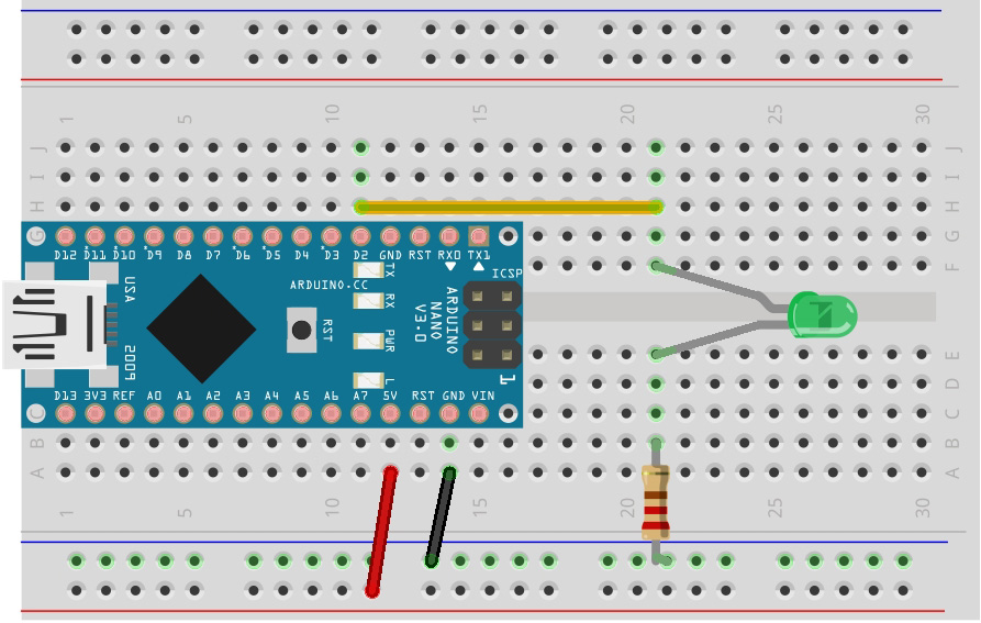
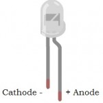
To build the circuit, attach a wire from pin 2 to the long leg of an LED (the positive leg, called the anode). Then attach a 220-ohm resistor from the short leg of the LED (the negative leg, called the cathode) to the outside ground rail. Connect a wire from the outside ground rail to the GND pin to complete the circuit. Then plug your GCDuino board into your computer select Arduino Nano as the board and the correct com port then click “Run on Arduino”.
Or if using the Arduino IDE, copy and paste the code below into it and upload following the previous instructions..
CODE:
You should now have your first bit of code blinking an LED. Congratulations!
In the program above, the first thing you do is create a variable to give the pin number an easy to recognise name, this makes your code easier to understand.
(The const keyword means it will be constant)
const byte led = 2;
Now we initialise pin 2 as an output pin using the name we gave it with the line
pinMode(led, OUTPUT);
In the main loop, you turn the LED on with the line:
digitalWrite(led, HIGH);
This supplies 5 volts to pin 2. That creates a voltage difference across the pins of the LED, and lights it up. Then you turn it off with the line:
digitalWrite(led, LOW);
That takes pin 2 back to 0 volts, and turns the LED off. In between the on and the off, you want enough time for a person to see the change, so the delay() commands tell the GCDuino to do nothing for 1000 milliseconds, or one second. When you use the delay() command, nothing else happens for that amount of time.
You can name a variable whatever you like but remember to make it easy to read. Good examples are redLED, blueLED, LED1, onLED, offLED, etc.
EXTRAS:
Can you add in the on board LED on pin 13?
How fast can you make them flash and still see it?