
The GCDuino is an Arduino UNO compatible clone based on the Atmel Atmega328P micro controller. It’s designed to be plugged straight into a breadboard. It allows users to easily and quickly learn to prototype electronic circuits. Also, its small form factor makes it ideal for stand alone applications.
Getting Started Guide.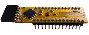
Congratulations on your GCDuino purchase. This page will guide you through the process of installing the required software and drivers, plugging your GCDuino in, and uploading your first program.
1) Download and install the Arduino IDE following the information on arduino.cc (Linux users, use your package manager).
2) Connect the programmer to your PC. If it doesn’t automatically install the drivers you can download them from silabs.com. Just scroll down the page, click the download VCP link next to your operating system and follow the installers instructions.
3) Attach your GCDuino to the breadboard.
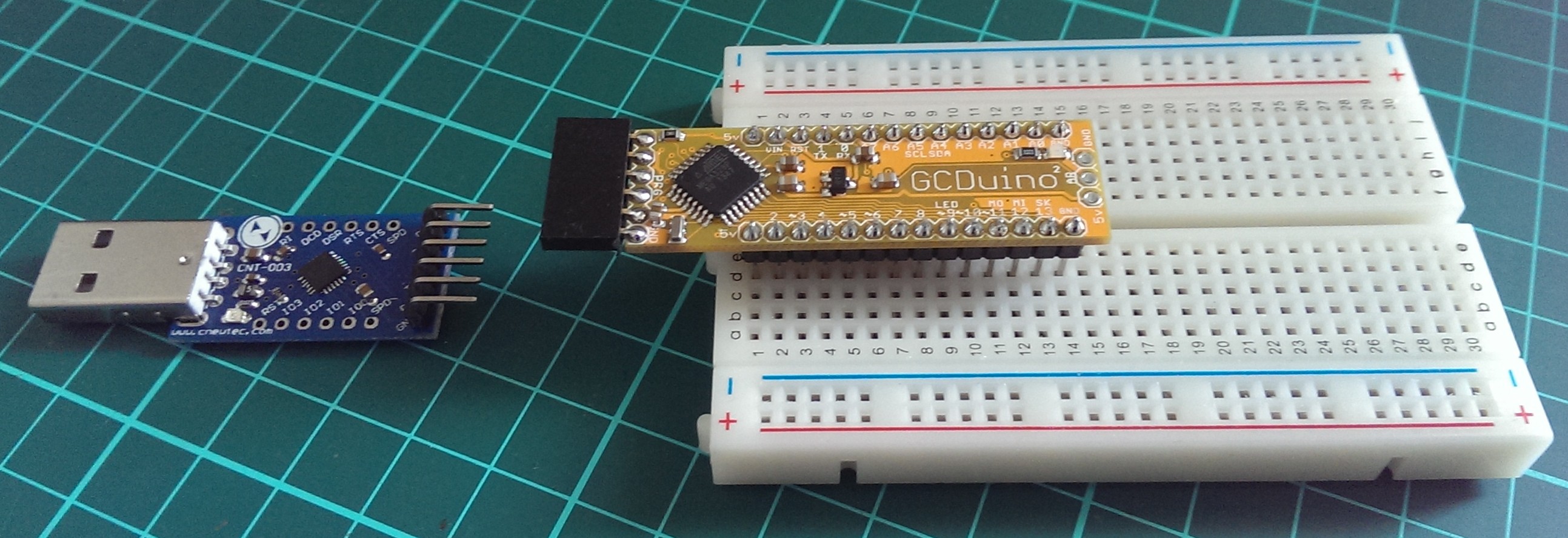
The pin numbers 2 to 13 will line up with the numbers on the breadboard.
4) Connect the programmer to the GCDuino.
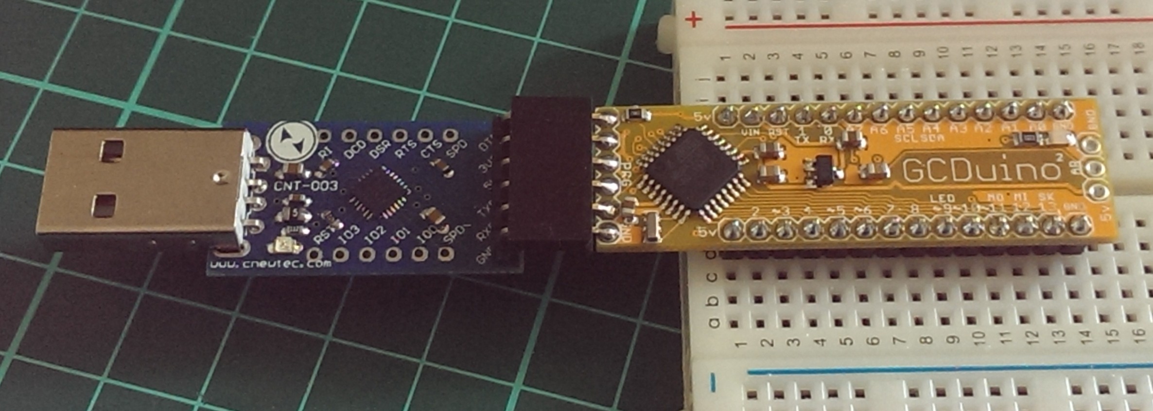
Connect it to your PC using the supplied USB extension cable. The LED should start to flash.
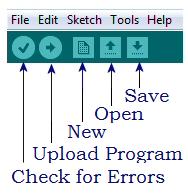
5) Open the Arduino IDE. This is the software used to program the GCDuino.![]()
a) Select “Arduino UNO” from the “Tools”, “Boards” menu.

b) Select the COM port for the programmer from the “Tools”, “Serial Port” menu. It will disappear if you unplugged your programmer.
6) Load the “Blink” Example. It’s located in the “File” menu, under “Examples”, “01.Basics”.
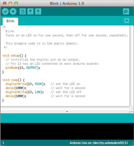
Replace the number “13” with the number “9”. This is the digital pin that the on board LED is connected to.
Change the number “1000” to a lower number. Try “20”. This number is milliseconds, so 20 is REALLY fast.
7) Upload your new code by clicking the “Upload” button.
Congratulations! You’ve just made some hardware do what you want. Try some of our example to learn more.
Notes:
The pin numbers 2 to 13 are all digital pins. You can turn them ON/OFF with the command “digitalWrite(pinNumber, HIGH);”, where pinNumber is replaced with the actual number, and HIGH (on) could also be LOW (off). You can also see what state (HIGH/LOW) a pin is using “digitalRead(pinNumber);”
Pins A0 to A7 are all analog Input pins. When you call “analogRead(pinNumber);” on one of these pins you can see how much voltage is on the pin, where 0 = 0v and 1023 = 5v.
Pins 1 (Tx) and 0 (Rx) are used for programming the GCDuino. Only use these pins if you know what you are doing.
Pin 9 has the on board LED. The “~” symbol in front of the pin number defines it as a PWM enabled pin. You’ll learn about PWM later.
The “AR” pin, located in the centre at the end of the GCDuino, is the Analog Reference Pin.
Here is a useful pinout diagram for the GCDuino.
Happy Hacking