
The first 3 Circuits are to help you understand the basics, you will use this information for EVERY project you ever build.
The essential, need to know, electronics principles to get you get started.
A Complete Circuit
For any circuit to work it must have one side connected to power and the other connected to ground.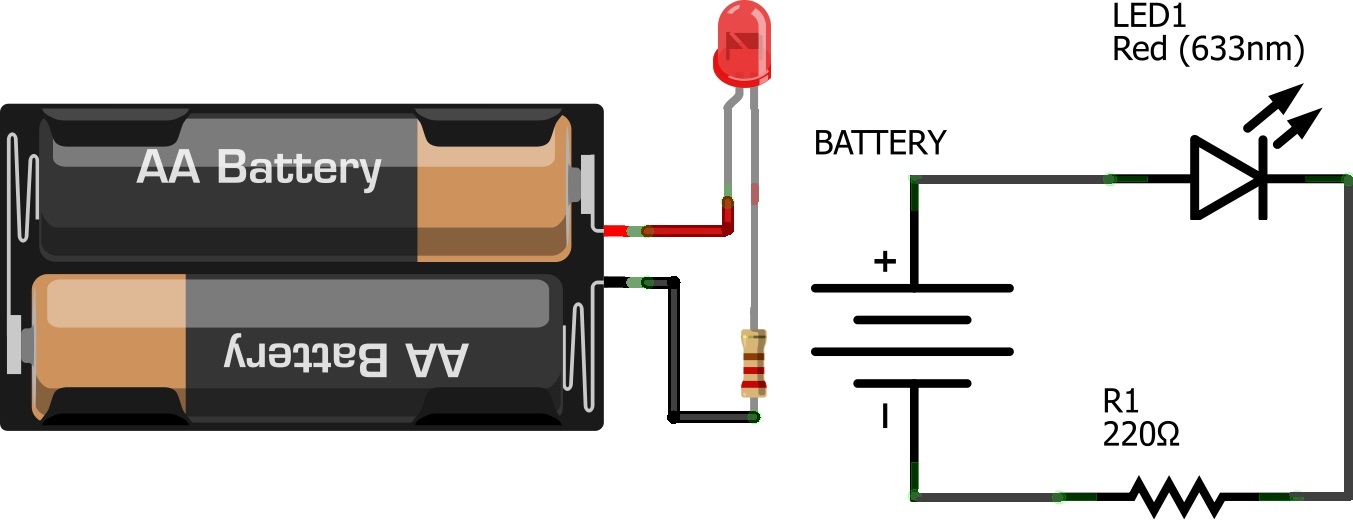
With micro controllers we can use 1 pin as the positive side of the circuit and connect the negative side to ground.
Making Connections
To make the connections of a circuit, we use a breadboard. Breadboards have conductive clips inside that firmly hold your wires and components in place.
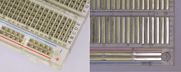
If you have a look at your breadboard you will notice that the rows are numbered. The 5 holes in each row (either side of the ravine) are connected together, so any components and wires you place in the same row will be connected. The long columns running down the sides of the breadboard are referred to as power rails, you connect 5v and ground to them to allow you to complete circuits easily.
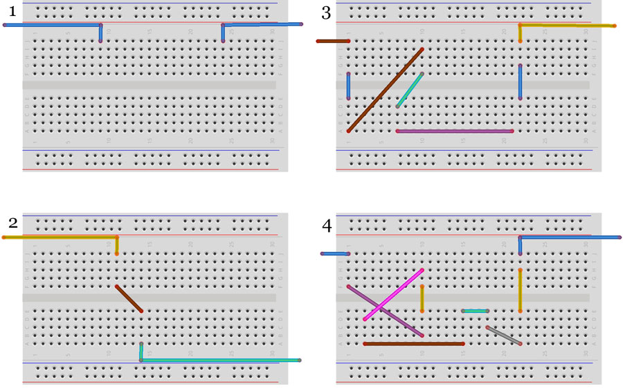
Question 1: Which of the following circuits connects the left side to the right side?
Circuit 1: Basic LED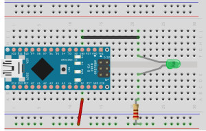
In this circuit the LED will constantly be ON.
We are connecting from the Arduino Nano’s 5v line to the power rail (red wire), from the power rail through the 220 Ohm resistor to the long leg of the LED, and finally from the short LED leg to GND or Ground.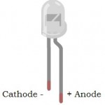
Light Emitting Diodes
LEDs are output devices, they have 2 legs and can only be connected one way. The long leg is called the Anode and is connected to the positive while the short leg is called the Cathode and connects to ground.
Resistor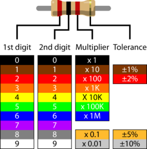
Limit the amount of current flowing around the circuit. The colours let you know the value. We used a Red, Red, Brown. So first and second digits are 2 and 2 times 10 = 220 Ohm. The chart shows a Red, Black, Red, So 1st digit = 2, 2nd = 0, Multiplier = 100. 20 x 100 = 2000 or 2k Ohm.
The higher the value resistor the less current will flow and the dimmer the LED will be. This is part of OHM’s Law, advanced people might want to check out Sparkfun’s tutorial on the subject.
For those that just want to get started: always use a 220 resistor with every LED when supplied by 5v. Otherwise you might burn out the LED or worse, the Arduino Nano.
Question 2: You also have a Brown, Black, Orange resistor in your kit. What is it’s Value?
Question 3: What happens to the LED if you swap the Red, Red, Brown Resistor with the Brown, Black, Orange one?
Circuit 2: LED with a button
A button is an input device. It completes the circuit and allows current to flow when pressed, lighting up the LED. Note: Make sure to swap back to the 220 Ohm resistor.
Buttons have 4 legs. The legs furthest apart on one side are connected together inside it.
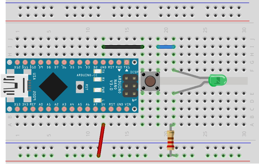
Circuit 3: LDR or Light Dependent Resistor

In this Circuit we replace the resistor with a LDR. A Light Dependent Resistor changes its value according to the brightness of the ambient light. The less light the higher the resistance. When you build this circuit, hold the button down and try putting your finger over the LDR or shinning a torch on it.
Now we get to the fun stuff….
Answers:
- Q1) 2 and 4
- Q2) 10k or 10,000 Ohms
- Q3) It goes very dim.